1) selection of electronic components
In order to study the thermohaline circulation,
we decided to integrate sensors salinityand temperature. Since we
are in the case of a deep
stream we placed the sensors at different
depths. Moreover, it was added a light
sensor to see if we
are the day ornight. For practical
conditions, a humidity
sensor will be installed inside the buoy to bepersuaded of its tightness.
Definition of a sensor : it allows the collection
of information from analog in
nature orelse can translate into the desired
language for the purpose of a study.
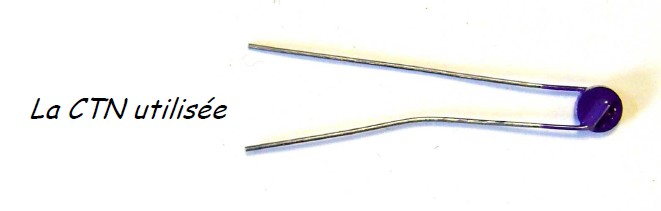
The temperature sensors used :
The NTC used
We use thermistor sensors
because they are
easy to use and inexpensive. They are
infact simple ohmic resistance value varies
whose conductors with temperatures. For
NTC (Negative Temperature Coefficient) used when
the temperature increaser, the
resistance value decreases.
The light sensors used :
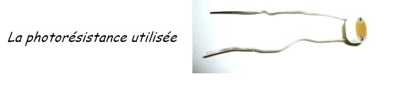
The photoresist used
We use as photoresists are also easy
to
use sensors that operate on the same principle
as thermistors. These drivers are the ohmic value of resistance varyaccording to light
intensity. When light
intensity increases the resistance valuedecreases.
The salinity sensor used :
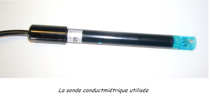
The sensor that we
use to
measure the salinity is a simple meter. Indeed, during ourresearch to find a way to
measure the salinity of seawater,
we found that sea water ismainly composed
of water and salt or sodium and chloride ions. Ions and otherelements being potentially present in
a generally negligible in view
of their quantity.
Clarified this point, we had
to find the instrument
used to measure the mass concentration
of salt. The ideal conductivity had to be
resistant to sea water andenvironmental
insults. In addition, our assembly had an energy
source delivering acontinuous current,
and therefore unusable for the conductivity probe (due toelectrolysis caused
by a constant
voltage across the conductivity). An interesting probechloride was commissioned a U.S. company, but before too
long delays in its
acquisition, it was finally abandoned. We had been
delayed ...
In the end, and the advice of knowledgeable people,
we learned that theconductometric sensors used in
high school HEITO brand could be
used since theywere powered by an alternating
current through the casing of
the meter. Analog
output0-5 V is already present on
the case, it only
remained to connect via a calibration of
the output voltage to the conductance of
different solutions of salt water.
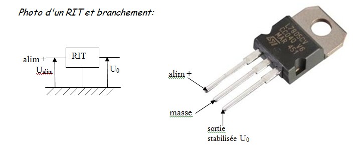
2) Electronic editing associated with resistive sensors
The power of our system
to be autonomous, so use the batteries in
series (6x1, 5V).However, the terminal
voltage of these batteries may vary as
and a measure of timewhich is annoying
because if the voltage changes, all the
voltages across resistorsexchange (according to the
law of associativity voltages). That
is why we
include in thecircuit, RIT (Integrated Voltage Regulator) which allows
us to have a constant voltage at
the output of the battery always
equal to U0 = 5.0 V.
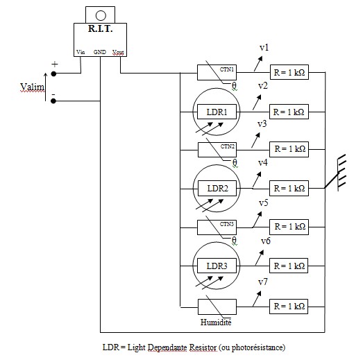
At the end of
the ITL, just plug in our series resistive
sensor and
a conductor ohmicresistance R = 1 kohms.
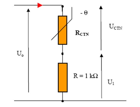
For example, in the
case of the thermistor, U0 is
constant, varying
with temperatureRCTN, U1 = U0 - UCTN will also
vary with temperature (but in reverse). It
is this voltage across the fixed resistor to
be sent
to the box end of HERA be encoded and
transmitted via satellite.
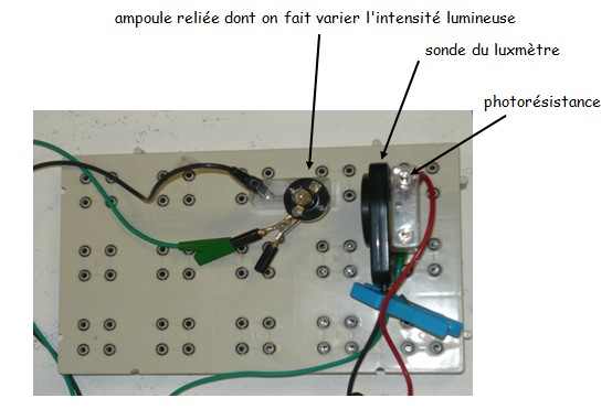
Here
is an illustration of the assembly of resistive
sensors. The 7 sensors connected tothe
ITL and the 7 links to the first
7 channels of
acquisition of housing HERA. The 8thtrack is that of the
voltage from the meter.
3) Calibration
a) Thermistor
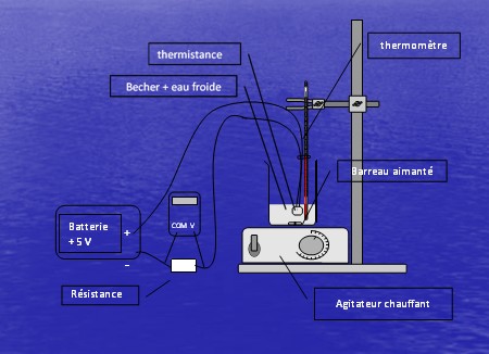
We completed the installation below in order
to calibrate our temperature
sensor. Wecalibrated the sensor using
a temperature range from 2 to 30
° C because she coversso the temperatures that
we find in actual
conditions along the Gulf Stream.
Here
are the results graphically, with the equation
relating the voltage U across thefixed
resistor as a function of temperature T :
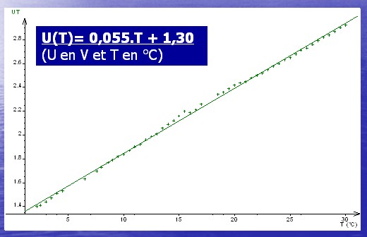
The voltage is measured
across the fixed resistor, we obtain an increasing
function of temperature.
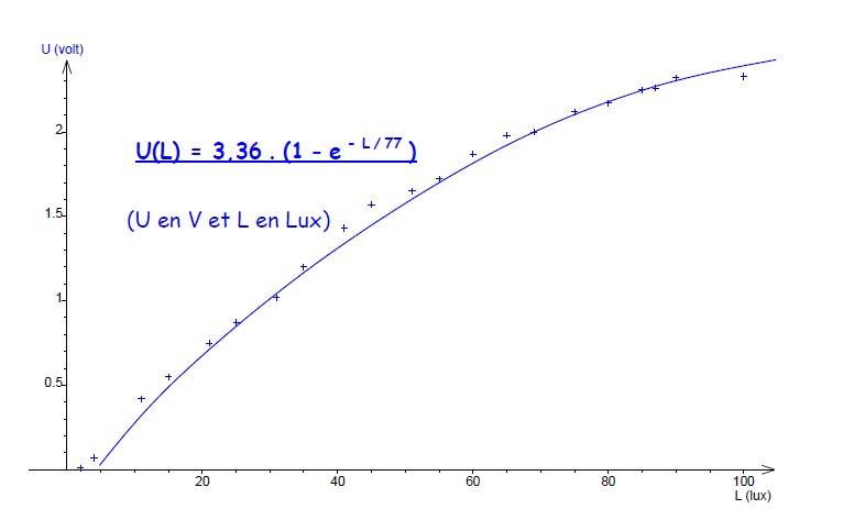
b) Photoresist
Here
are the results graphically, with the equation
relating the voltage U across thefixed
resistor depending on the illumination L :
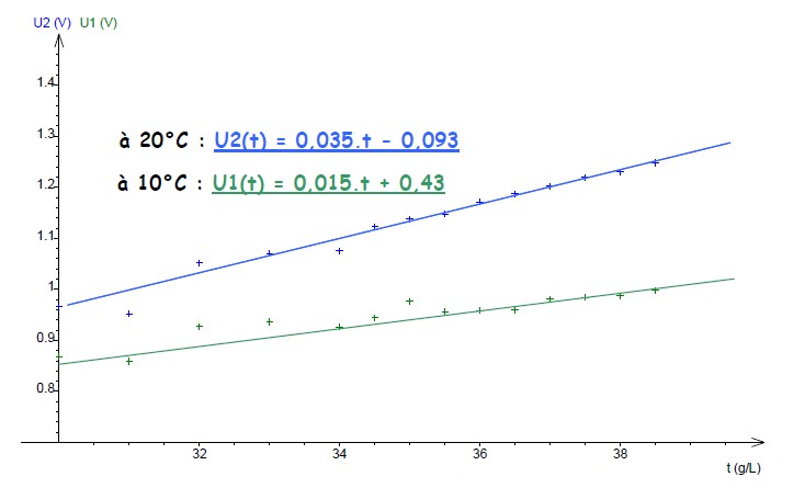
c) Conductivity
The case of conductivity with an analog
output ranging from 0 to 5V depending
on theconductivity of the
solution, we performed the calibration of the latter with a
solution ofsodium chloride (Na +, Cl-) following a mass concentration
range from 30 g / L to 39 g/ L because it covers and the
concentrations that we find in actual
conditions along theGulf Stream. It has also been set in
advance the cell constant with a solution of
potassium chloride (calibration solution to a
conductivity provided by the manufacturer).
Conductivity depending on temperature, we performed
measurements at two different temperatures: one at 10
° C where the voltage is measured and at
20 ° C where the measured voltage is U2. Here
are the results graphically, with the equation
relating thevoltage U to the output of the
box sets of conductivity as a
function of mass t (g / L) ofthe solution :
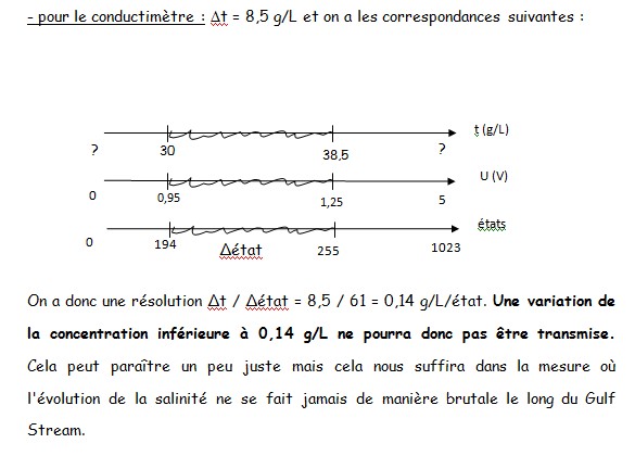
4) Resolution and accuracy of the system
The resolution
is the minimum change in our system of
sensors can detect. She is
about 5 mV after the sheet manufacturer HERA. Indeed, the case allows voltage
measurements between 0 and 5 V and the
voltage measured is coded in binary on
10bits (ie 0 to 1023 different states) and
then sent via satellite. The resolution
is therefore5 / 210 = 5 / 1024 =
0.0048 V is about 5 mV. A voltage
variation less
than ΔU = 5 mVcan not be transmitted.
Determine the resolutions of each sensor :
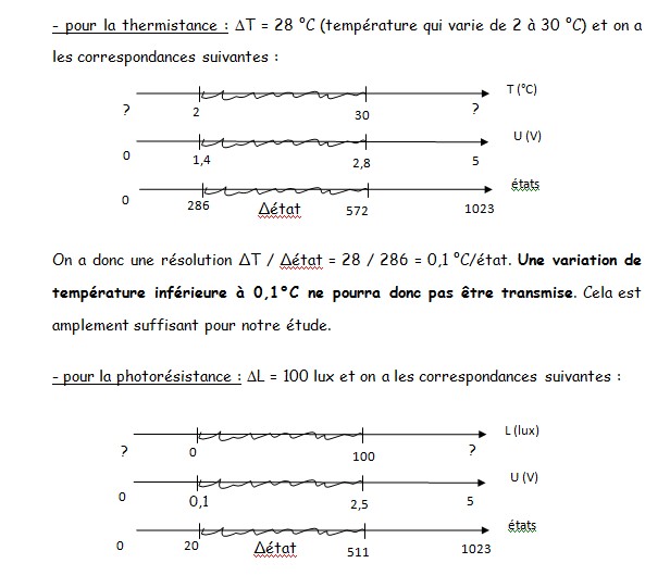
It has a
resolution DELTA.L / Δétat = 100/491 = 0.2 lux condition. A variation of less
than 0.2 lux illumination can not be transmitted. This is amply sufficient for
our study as we seek
to make measurements for different depths and
observe the day / night.
The accuracy of our sensors depends largely
on the
quality of our calibration and thereference standard was used (the thermometer,
for example). Even if it is certain that
we can measure very precise values, what
matters is to observe the differencebetween the
values at
different depths in different places and
especially the Gulf Stream.